Architecture Design
The architecture can be modeled using a variety of different models. This page will provide examples of the following architectural model diagrams:
- Structural View Model
- Deployment View Model
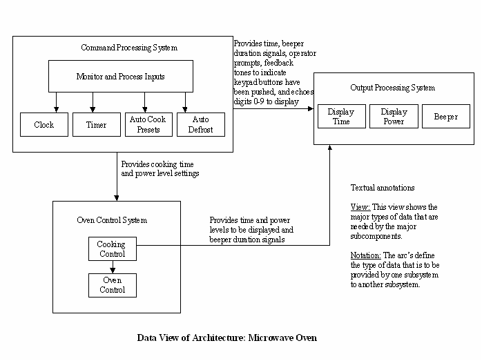
- Data View Model
- Layered View Model
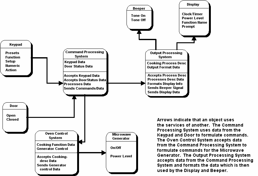
- Object-oriented Decomposition View
- Statechart Model
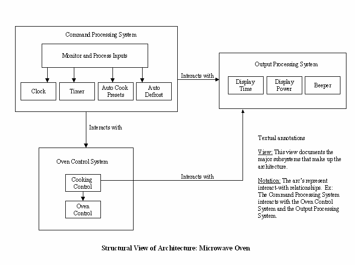
Structural View Model

Data Dictionary:
Every diagram needs to have a data dictionary as supporting documentation. The data dictionary cleary explains the entities that are depicted in the diagram. The data dictionary for the above diagram follows:|
Term |
Description |
Type |
Requirements Trace |
|
Auto
Cook Presets |
Processes
input data containing manufacturer-defined presets for heating common food
items. |
Sub-system |
|
|
Auto
Defrost |
Processes
input data containing power level and time for defrosting frozen food item. |
Sub-system |
|
|
Beeper |
Processes
output signals to the beeper device. |
Sub-system |
|
|
Clock |
Processes
input data containing clock-setting parameters. |
Sub-system |
F4.1.1,
F4.1.2, F4.1.3, F4.1.4, F4.1.5, F4.1.6, F4.1.7, F4.1.8, F4.1.9 |
|
Command
Processing |
Processes
all inputs from the user. |
System |
|
|
Cooking
Control |
Processes
output data from Command Processing System and sends command signals to the Oven
Control sub-system. |
Sub-system |
F4.3.3,
F4.4.6, F4.5.6, F4.5.7, F4.5.8, F4.5.9, F4.5.11, F4.5.12 |
|
Display
Power |
Processes
output data containing the current power level that is encoded for display on
the LCD. |
Sub-system |
|
|
Display
Time |
Processes
output data containing the current time of day value that is encoded for
display on the LCD. |
Sub-system |
F4.1.1, F4.1.2, F4.1.3, F4.1.4, F4.1.5, F4.1.6, F4.1.7, F4.1.8, F4.1.9 |
|
Monitor
/ Process Inputs |
Processes
pre-processed inputs and controls system state based on those inputs. |
Sub-system |
|
|
Output
Processing |
Processes
output data and converts it to signals and codes that can be used by the
target output devices. |
System |
F1,
F2, F4.1.4, F4.1.7, F4.1.8, F4.1.9, F4.2.5, F4.2.6, F4.2.7, F4.2.9, F4.3.3, F4.4.3,
F4.4.5, F4.5.5, F4.5.7, F4.5.8, F4.5.10, F4.5.11, F5, F6 |
|
Oven
Control (sub-system) |
Processes
data sent from the Cooking Control sub-system and converts the data into the
correct format for the cooker component. |
Sub-system |
F4.3.3,
F4.4.6, F4.5.6, F4.5.7, F4.5.8, F4.5.9, F4.5.11, F4.5.12 |
|
Oven
Control (system) |
Processes
output data and converts it to signals that can be used by the cooker
component. |
System |
F4.3.3, F4.4.6, F4.5.6, F4.5.7, F4.5.8, F4.5.9, F4.5.11, F4.5.12 |
Deployment View Model

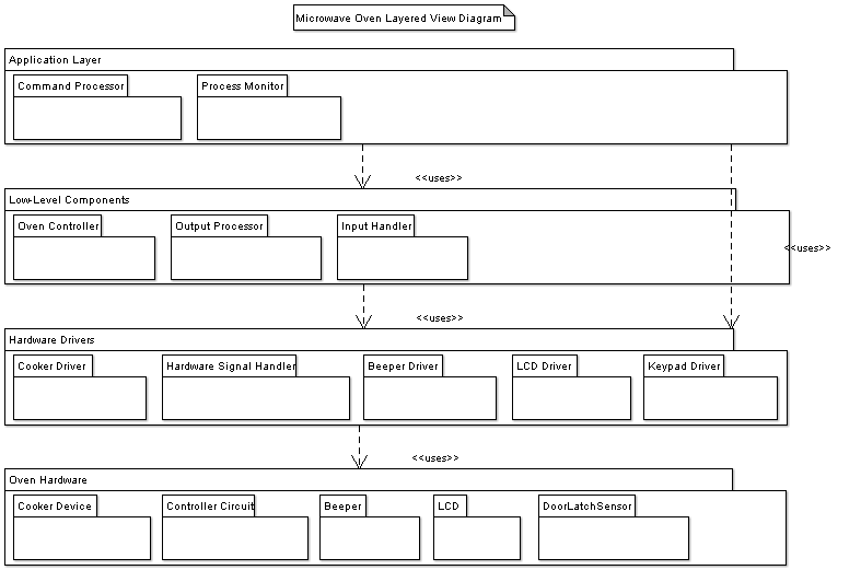
The process monitor component and the hardware signal handler component work together to fulfill non-functional requirement N9. The hardware signal handler will capture power tolerance errors from sent from the hardware sensors and will convey them to the process monitor so that the system can handle the error appropriately by displaying the error to the user via the LCD screen. The hardware signal handler is a multi-purpose component in that it reports various types of hardware signals including signals from the microwave door latch sensor.
Data Dictionary:
|
Term |
Description |
Type |
Requirements Trace |
|
Beeper
Driver |
Generates
output signals to the beeper device. |
Sub-component |
|
|
Command
Processor |
Processes
commands entered by the user and controls the oven devices according to the
command given within the constraints of the current state of the system. |
Sub-component |
F4.1.3,
F4.1.5, F4.1.6, F4.2.1, F4.2.3, F4.2.4, F4.2.7, F4.2.8, F4.2.9, F4.3.3, F4.4.4,
F4.4.6, F4.5.1, F4.5.3, F4.5.6, F4.5.7, F4.5.9, F4.5.10 |
|
Controller |
Processes
system inputs and controls system state based on those inputs. |
Component |
|
|
Cooker
Driver |
Generates
output signals to the cooker device. |
Sub-component |
F4.3.3,
F4.4.6, F4.5.6, F4.5.7, F4.5.8, F4.5.9, F4.5.11, F4.5.12 |
|
Hardware
Signal Handler |
Handles
input signals from hardware components and sends correctly formatted data to
the Controller. |
Sub-component |
|
|
Input
Handler |
Handles
input data from the keypad as well as from oven components such as the cooker
component and the door latch sensor. |
Component |
|
|
Keypad
Driver |
Handles
all inputs from the keypad. |
Sub-component |
F1,
F4.1.1, F4.1.5, F4.1.6, F4.2.1, F4.2.3, F4.2.4, F4.2.7, F4.2.8, F4.2.9, F4.3.2,
F4.3.3, F4.4.5, F4.4.6, F4.5.1, F4.5.3, F4.5.6, F4.5.7, F4.5.9, F4.5.10 |
|
LCD
Driver |
Generates
output signals to the cooker device. |
Sub-component |
F4.1.1,
F4.1.2, F4.1.3, F4.1.4, F4.1.5, F4.1.6, F4.1.7, F4.1.8, F4.1.9, F4.3.2,
F4.3.3, F4.4.1, F4.4.2, F4.5.1, F4.5.2 |
|
Output
Processor |
Generates
output data and converts it to signals and codes that can be used by the beeper
and LCD output devices. |
Component |
F4.1.1,
F4.1.2, F4.1.3, F4.1.4, F4.1.5, F4.1.6, F4.1.7, F4.1.8, F4.1.9, F4.2.5, F4.3.2,
F4.3.3, F4.4.1, F4.4.2, F4.5.1, F4.5.2, F4.5.8, F4.5.10, F4.5.11 |
|
Oven
Controller |
Processes
output data and converts it to signals that can be used by the cooker
component. |
Component |
F4.3.3,
F4.4.6, F4.5.6, F4.5.7, F4.5.8, F4.5.9, F4.5.11, F4.5.12 |
|
Process
Monitor |
Processes
signals from hardware components, monitors the status of other system
components, and controls the oven devices according the current state of the
system. |
Sub-component |
Data View Model

Data Dictionary:
(Same as for Structural View Model above.)Layered View Model

Data Dictionary:
(Same as for Deployment View Model above.)Data Dictionary:
|
Term |
Description |
Type |
Requirements Trace |
|
Accepts
Cooking-desc Data |
Oven
Control System operation that accepts cooking data. |
Method |
|
|
Accepts
DoorStatus Data |
Command
Processing System (Controller) operation that accepts data from the door
sensor. |
Method |
|
|
Accepts
Keypad Data |
Command
Processing System (Controller) operation that accepts keycode data from the
keypad. |
Method |
|
|
Accepts
Process Desc |
Output
Processing System operation that accepts process-related data. |
Method |
F3,
F4, F4.1.1, F4.1.2, F4.1.3, F4.1.4, F4.1.5, F4.1.6, F4.1.7, F4.1.8, F4.1.9,
F4.2.1, F4.2.6, F4.2.7, F4.3.1, F4.3.3, F4.4.1, F4.4.2, F4.4.3, F4.4.4,
F4.4.5, F4.4.6, F4.5.5, F4.5.7, F4.5.8, F5, F6 |
|
Action |
Keypad
action key. |
Attribute |
|
|
Beeper |
Beeper
entity that encapsulates beeper attributes. |
Class |
|
|
Clock
/ Timer |
Clock
and Timer attributes of the Display entity. |
Attribute |
F4.1.1,
F4.1.2, F4.1.3, F4.1.4, F4.1.5, F4.1.6, F4.1.7, F4.1.8, F4.1.9, F4.2.1,
F4.2.6, F4.2.7 |
|
Closed |
Status
attribute of the Door class. |
Attribute |
|
|
Command
Processing System |
Controller
entity that encapsulates controller object attributes and operations. |
Class |
|
|
Cooking
Function Data |
Oven
Control System attribute that identifies the cooking function selected. |
Attribute |
|
|
Cooking
Process Desc |
Output
Processing System attribute that contains cooking process-related data. |
Attribute |
F3, F4, F4.1.1, F4.1.2, F4.1.3, F4.1.4, F4.1.5, F4.1.6, F4.1.7, F4.1.8, F4.1.9, F4.2.1, F4.2.6, F4.2.7, F4.3.1, F4.3.3, F4.4.1, F4.4.2, F4.4.3, F4.4.4, F4.4.5, F4.4.6, F4.5.5, F4.5.7, F4.5.8, F5, F6 |
|
Display |
Display
entity that encapsulates display object attributes. |
Class |
F3, F4, F4.1.1, F4.1.2, F4.1.3, F4.1.4, F4.1.5, F4.1.6, F4.1.7, F4.1.8, F4.1.9, F4.2.1, F4.2.6, F4.2.7, F4.3.1, F4.3.3, F4.4.1, F4.4.2, F4.4.3, F4.4.4, F4.4.5, F4.4.6, F4.5.5, F4.5.7, F4.5.8, F5, F6 |
|
Door |
Door
entity that encapsulates door object attributes. |
Class |
|
|
Door
Status Data |
Command
Processing System (Controller) attribute that contains door status data. |
Attribute |
|
|
Formats
Display Info |
Output
Processing System operation that formats data that will be sent to the
display device. |
Method |
F3, F4, F4.1.1, F4.1.2, F4.1.3, F4.1.4, F4.1.5, F4.1.6, F4.1.7, F4.1.8, F4.1.9, F4.2.1, F4.2.6, F4.2.7, F4.3.1, F4.3.3, F4.4.1, F4.4.2, F4.4.3, F4.4.4, F4.4.5, F4.4.6, F4.5.5, F4.5.7, F4.5.8, F5, F6 |
|
Function |
Keypad
Function key. |
Attribute |
|
|
Function
Name |
Attribute
of the Display entity that contains the name of the selected function. |
Attribute |
|
|
Generator
Control |
Oven
Control System attribute that contains the control codes for the generator. |
Attribute |
|
|
Keypad |
Keypad
entity that encapsulates keypad object attributes. |
Class |
|
|
Keypad
Data |
Command
Processing System (Controller) attribute that contains keycode data from the
keypad. |
Attribute |
|
|
Microwave
Generator |
Microwave
Generator (cavity magnetron) entity that encapsulates generator object
attributes. |
Class |
|
|
Numeric |
Keypad
Numeric key. |
Attribute |
|
|
On/Off |
Microwave
Generator class attribute that contains the current status of the generator. |
Attribute |
|
|
Open |
Status
attribute of the Door class. |
Attribute |
|
|
Output
Processing System |
Output
Processing System entity that encapsulates output processing system object
attributes and operations. |
Class |
F3, F4, F4.1.1, F4.1.2, F4.1.3, F4.1.4, F4.1.5, F4.1.6, F4.1.7, F4.1.8, F4.1.9, F4.2.1, F4.2.6, F4.2.7, F4.3.1, F4.3.3, F4.4.1, F4.4.2, F4.4.3, F4.4.4, F4.4.5, F4.4.6, F4.5.5, F4.5.7, F4.5.8, F5, F6 |
|
Power
Level |
Microwave
Generator class attribute that contains the current power level of the
generator. |
Attribute |
F4.3.1,
F4.3.2, F4.4.1, F4.4.2, F4.4.3, F4.4.6, F4.5.1, F4.5.2, F4.5.10, F4.5.12 |
|
Power
Level |
Attribute
of the Display entity that contains the power level selected by the user. |
Attribute |
F4.3.1, F4.3.2, F4.4.1, F4.4.2, F4.4.3, F4.4.6, F4.5.1, F4.5.2, F4.5.10, F4.5.12 |
|
Presets |
Keypad
Preset key. |
Attribute |
|
|
Processes
Data |
Command
Processing System (Controller) operation that processes input data. |
Method |
|
|
Processes
Desc Data |
Output
Processing System operation that processes descripton data. |
Method |
F3, F4, F4.1.1, F4.1.2, F4.1.3, F4.1.4, F4.1.5, F4.1.6, F4.1.7, F4.1.8, F4.1.9, F4.2.1, F4.2.6, F4.2.7, F4.3.1, F4.3.3, F4.4.1, F4.4.2, F4.4.3, F4.4.4, F4.4.5, F4.4.6, F4.5.5, F4.5.7, F4.5.8, F5, F6 |
|
Prompt |
Attribute
of the Display entity that contains the prompt data to be displayed. |
Attribute |
|
|
Sends
Beeper Signal |
Output
Processing System operation that sends signals to the beeper device. |
Method |
|
|
Sends
Commands / Data |
Command
Processing System (Controller) operation that sends commands and data to the
necessary components to maintain a valid system state. |
Method |
|
|
Sends
Display Data |
Output
Processing System operation that sends signals to the display device. |
Method |
F3, F4, F4.1.1, F4.1.2, F4.1.3, F4.1.4, F4.1.5, F4.1.6, F4.1.7, F4.1.8, F4.1.9, F4.2.1, F4.2.6, F4.2.7, F4.3.1, F4.3.3, F4.4.1, F4.4.2, F4.4.3, F4.4.4, F4.4.5, F4.4.6, F4.5.5, F4.5.7, F4.5.8, F5, F6 |
|
Sends
Generator control Data |
Oven
Control System operation that sends the control data / signals to the
generator. |
Method |
|
|
Tone
Off |
Attribute
of the Beeper entity that contains the status of the beeper device. |
Attribute |
|
|
Tone
On |
Attribute
of the Beeper entity that contains the status of the beeper device. |
Attribute |
Statechart (State Machine) Model
A description of statechart diagrams was given earlier in this software development process on the "Create System Model" page. This section contains an excellent example of a statechart diagram that was re-created from a figure in Ian Sommerville's book, Software Engineering (This text is referenced on the "References" page of this website). The following statechart diagram models the cooking operation of a microwave oven using simple and composite states.
Data Dictionary:
The information contained in the following data dictionary tables was taken verbatim from Ian Sommerville's book, Software Engineering (This text is referenced on the "References" page of this website).|
State |
Description |
|
Waiting |
The oven is
waiting for input. The display shows the current time. |
|
Half power |
The oven power is
set to 300 watts. The display shows ‘Half power’. |
|
Full power |
The oven power is
set to 600 watts. The display shows ‘Full power’. |
|
Set time |
The cooking time
is set to the user’s input value. The display shows the cooking time selected
and is updated as the time is set. |
|
Disabled |
Oven operation is
disabled for safety. Interior oven light is on. Display shows ‘Not ready’. |
|
Enabled |
Oven operation is
enabled. Interior oven light is off. Display shows ‘Ready to cook’. |
|
Operation |
Oven in operation.
Interior oven light is on. Display shows the timer countdown. On completion
of cooking, the buzzer is sounded for 5 seconds. Oven light is on. Display
shows ‘Cooking complete’ while buzzer is sounding. |
|
Stimulus |
Description |
|
Half power |
The user has
pressed the half power button |
|
Full power |
The user has
pressed the full power button |
|
Timer |
The user has
pressed one of the timer buttons |
|
Number |
The user has
pressed a numeric key |
|
Door open |
The oven door
switch is not closed |
|
Door closed |
The oven door
switch is closed |
|
Start |
The user has
pressed the start button |
|
Cancel |
The user has
pressed the cancel button |
Now that we have completed the design of the architecture by modeling the basic structure of the microwave oven system, we can begin design of the system interfaces.
Note: This is clearly an abridged architectural design to make the content suitable for an instructional web page. It would make sense to have a more elaborate architectural design for a real project.
