Detailed Design
Note: As mentioned on the Interface Design page, many of the examples will be scoped to a particular part of the overall system under development. Detailed design artifacts are going to contain a large amount of details which, if included in full, would obscure the point of this page.
The detailed design should represent the system design in a variety of views where each view uses a different modeling technique. By using a variety of views, different parts of the system can be made clearer by different views. Some views are better at elaborating a systems states whereas other views are better at showing how data flows within the system. Other views are better at showing how different system entities relate to each through class taxonomies for systems that are designed using an object-oriented approach.
A template for detailed design would not be of much use since each detailed design is likely to be unique and quite different from other designs. What is helpful in regards to guidance on detailed design are examples. This page provides some detailed design content for the example microwave oven system that is referenced periodically by this website.
The major sections of this web page are the following:
- Structural Chart
- Control-Flow Model
- Class Diagram
- Collaboration Diagram
- Sequence Diagram
- Activity Diagram
- Pseudocode
- V-Model Diagram
Structural Chart
The intent of a structural chart is to specify the components (boxes) of the system under development along with the interactions (arcs) that take place between those components.The structural chart diagram below is an overall system diagram for the microwave oven example and is therefore has a very high information density.
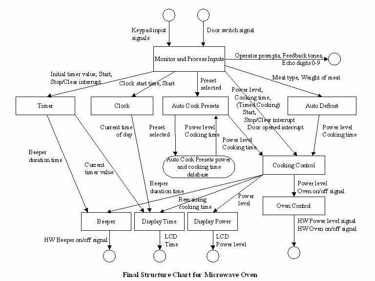
Data Dictionary:
|
Entity
Name |
Type |
Description |
|
Auto Cook Presets |
FUNCTION |
Looks up proper
power level and
cooking time settings for a given auto cook preset food item |
|
Auto Defrost |
FUNCTION |
Determines correct
power level
and cooking time values based on type of meat and weight of meat being
defrosted |
|
Beeper |
FUNCTION |
Sounds beeper tone
for
specified length of time |
|
Beeper duration
time |
INTEGER |
The number of
seconds that the
beeper is to sound a tone. |
|
Clock |
FUNCTION |
Begins measuring
time from an
initial time of day input |
|
Clock start time |
TIME_H_M |
Operator entered
time value
used to initialize the clock |
|
Cooking Control |
FUNCTION |
Sends signals to
set oven
control function to set proper power level then turn oven on for the
length of time specified in the input to this function |
|
Current time of day |
TIME_H_M |
Current time of
day to be
displayed |
|
Current timer value |
TIME_M_S |
Current timer
value to be
displayed |
|
Display Power |
FUNCTION |
Sends power level
setting to
LCD screen to be displayed |
|
Display Time |
FUNCTION |
Sends time setting
to LCD
screen to be displayed |
|
Door opened
interrupt |
ENUMERATION |
Door closed = 0,
Door open = 1 |
|
Door switch signal |
DOOR_SWITCH |
Signal from door
sensor to
indicate whether the microwave door is opened or closed |
|
Echo digits 0-9 |
ECHO_DIGITS |
Echo digits 0-9 to
LCD screen
as operator presses these keys |
|
Feedback tones |
FEEDBACK_TONES |
Sound tones after
each key is
entered |
|
HW Beeper on off
signal |
HW_BEEPER_CNTL |
Discrete signal to
beeper
hardware to turn beeper on and off |
|
HW Oven on off
signal |
HW_OVEN_CNTL |
Discrete signal to
microwave
generator hardware to turn oven on and off |
|
HW Power level |
HW_PWR_LEVEL |
Signal to set
microwave
generator hardware to correct value |
|
Initial timer value |
TIME_M_S |
The operator
entered time value
used to initialize the timer |
|
Keypad input
signals |
KEYPAD_INPUTS |
Input signals from
keypad
hardware |
|
LCD Power level |
LCD_PWR_LEVEL |
Power level
formatted for
display on LCD screen. |
|
LCD Time |
LCD_TIME |
Time value (XX:XX)
sent to LCD
screen (can be either in hours, minutes or in minutes, seconds
depending on which microwave function is active) |
|
Meat type |
ENUMERATION |
Type of meat (Beef
= 1, Poultry
= 2, Fish = 3) |
|
Monitor and
Process Inputs |
FUNCTION |
Receives and
decodes inputs
from keypad and door sensor then calls appropriate sub-functions |
|
Operator prompts |
OPER_PROMPT |
Operator prompts
sent to the
LCD screen to request operator inputs |
|
Oven on/off signal |
ENUMERATION |
Off = 0, On = 1 |
|
Oven Control |
FUNCTION |
Sends power level
settings to
microwave generator hardware then turns microwave generator hardware on
and off as inputs indicate |
|
Power level |
INTEGER |
Power level
selected by
operator (1 – 10) |
|
Preset selected |
ENUMERATION |
Preset key
selected by operator
(Popcorn = 0, Potato = 1, Beverage = 2, Pizza = 3, Frozen
Entrée = 4, Fresh Veg. = 5) |
|
Remaining cooking
time |
TIME_M_S |
Length of time
before cooking
completes |
|
Start |
ENUMERATION |
Indicates that the
Start button
has been pushed (Start active = 1, Start inactive = 0) |
|
Stop/Clear
interrupt |
ENUMERATION |
Stop/Clear button
indication
signal (Stop/Clear active = 1, Stop/Clear inactive = 0) |
|
Timer |
FUNCTION |
Receives an
initial timer value
then counts down the time to 00:00 and sends a signal to the beeper
function to sound a tone. |
|
Weight of meat |
FLOAT |
Weight of meat for
defrosting
in ounces |
Control-Flow Model
A Control-Flow Diagram (CFD) models the flow of execution through data objects. This is a venerable approach to specifying the flow design of a system with a great amount of precision. UML offers a collection of diagrams to convey the same type of system information. These diagrams are activity diagrams, collaboration (object-interaction) diagrams, and sequence diagrams.Each rhomboid represents a software object and each directed arc represents a single flow of control ordinally segmented according to the call sequences. The following control flow diagram models the control flow of the auto-defrost operation of the microwave oven example.
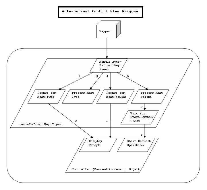
Data Dictionary:
|
Term |
Description |
Type |
Requirements
Trace |
|
Auto-Defrost
Key Object |
Process
scope of Auto-Defrost Key control flow. |
Process
Entity |
|
|
Controller
Object |
Process
scope of Controller control flow with respect to Auto-Defrost Key
interaction. |
Process
Entity |
|
|
Display
Prompt |
Process
within Controller Object processing scope that displays prompts for
requesters. |
Sub-Process
Entity |
|
|
Handle
Auto-Defrost Key Event |
Process
within Auto-Defrost Key Object processing scope that handles events as
they occur. |
Sub-Process
Entity |
|
|
Keypad |
Keypad
input device. |
Hardware
Component |
|
|
Process
Meat Type |
Process
within Auto-Defrost Key Object processing scope that processes data for
the meat type selected. |
Sub-Process
Entity |
|
|
Process
Meat Weight |
Process
within Auto-Defrost Key Object processing scope that processes data for
the meat weight selected. |
Sub-Process
Entity |
|
|
Prompt
for Meat Type |
Process
within Auto-Defrost Key Object processing scope that requests display
of meat type prompt. |
Sub-Process
Entity |
|
|
Prompt
for Meat Weight |
Process
within Auto-Defrost Key Object processing scope that requests display
of meat type prompt. |
Sub-Process
Entity |
|
|
Start
Defrost Operation |
Process
within Controller Object processing scope that communicates with the
generator to start cooking. |
Sub-Process
Entity |
|
|
Wait
for Start Button Press |
Process
within Auto-Defrost Key Object processing scope that waits for user
acknowledgement of selection via the start button event. |
Sub-Process
Entity |
Class Diagram
A class diagram is a superset of an inheritance model in that it models the class taxonomy; however, it also models relationships between the various class entities like a semantic model.A class diagram is a type of UML (Unified Modeling Language) diagram. A class diagram describes the various entities that will be used to construct the functioning system. Describing object (an object is an instantiated class much like a process is an instantiated program) attributes and operations allows the developer to begin to logically apportion data and functions in a fashion that is natural to human beings. Participating objects are defined via their classes (or templates). Their capabilities, their roles, and their associations / relationships are specified. By specifying the classes from which objects are created, a developer is essentially adding parts to a kit from which a fully functional system will be produced. This type of model is iterative. It may start with classes that only have names. As the developer's understanding of the problem improves, the developer can begin to add the necessary attributes and operations that the classes will need. In this way, the solution system is systematically developed increment by increment.
The following class diagram models the system inputs for the microwave oven example and is the same diagram displayed on the Interface Design page.
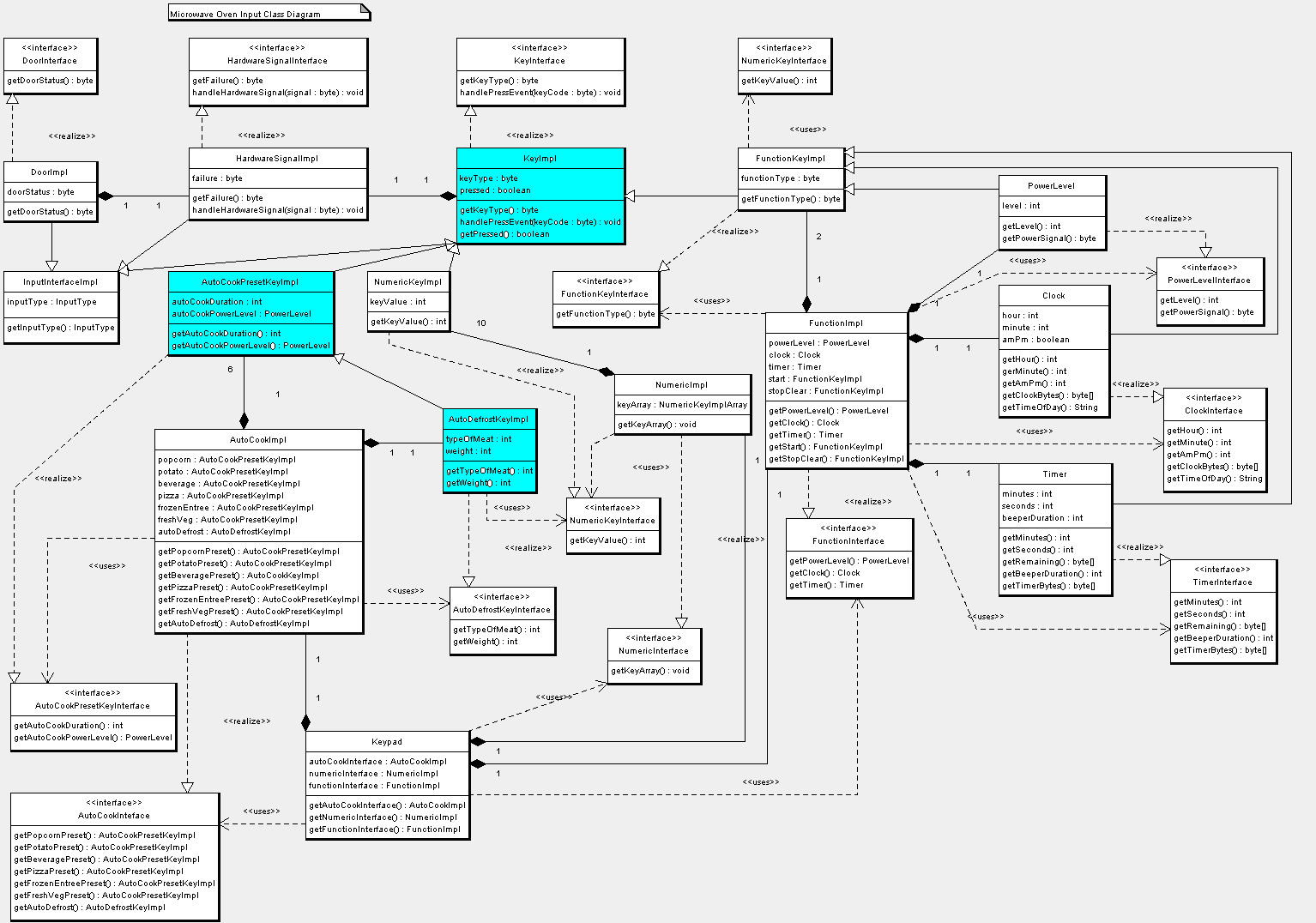
Data Dictionary:
Please refer to the data dictionary for this diagram on the Interface Design page.Collaboration Diagram
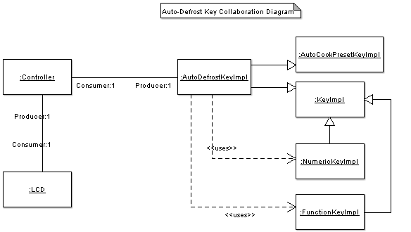
A collaboration defines a collaborative effort between cooperating objects. Again, an object is an instance of a class. The collaboration diagram models the interactions that take place between the colloborating objects to affect a desired end result.The following collaboration diagram models the interaction between objects that cooperate to provide the auto-defrost functionality for the microwave oven example.
Data Dictionary:
|
Term |
Description |
Type |
Requirements
Trace |
|
AutoCookPresetKeyImpl |
Parent
class object to AutoDefrostKeyImpl class object that contains and
processes cooking duration and power level data. |
Object |
|
|
AutoDefrostKeyImpl |
Class
object that contains and processes type of meat and meat weight data. |
Object |
|
|
Consumer |
Role
stereotype of object association that shows the object is a consumer of
data via the association arc. |
Association
Role |
|
|
Controller |
Class
object that manages controller data and system state and provides
services to other system objects. |
Object |
|
|
FunctionKeyImpl |
Class
object that is used (indirectly) by the AutoDefrostKeyImpl class
object. FunctionKeyImpl class object provides Start button
functionality. |
Object |
|
|
KeyImpl |
Parent
class object to AutoDefrostKeyImpl, FunctionKeyImpl, and NumericKeyImpl
class objects that maintains key state and handles key-press events. |
Object |
|
|
LCD |
Class
object that processes display data so that it is correct rendered on
the display screen. |
Object |
|
|
NumericKeyImpl |
Class
object that is used by the AutoDefrostKeyImpl class object.
NumericKeyImpl class object contains integer values of numeric keys
that have been pressed. |
Object |
|
|
Producer |
Role
stereotype of object association that shows the object is a producer of
data via the association arc. |
Association
Role |
|
Sequence Diagram
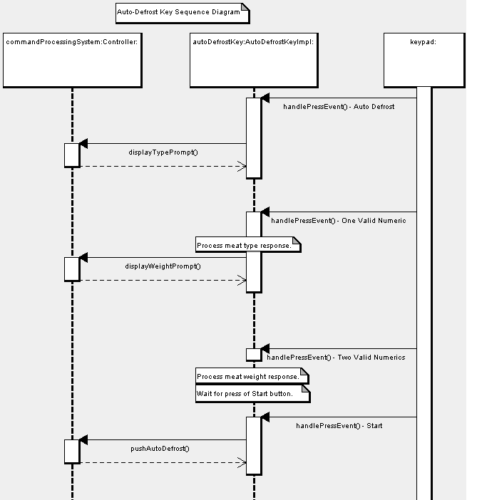
Sequence diagrams model the sequence of interactions between collaborating objects with the arrow of time pointing downwards. The first interaction or call would be at the top of the diagram just below the object squares. The second interaction would be the next call down and so on. Sequence diagrams are sometimes informally referred to as "lollipop diagrams" since the objects are shown as squares with long stems hanging down thus giving them the appearance of a lollipop. The reason for this odd type of symbol is that the interactions need to be drawn between objects in swimlanes so that the vertical spatiality of the diagram is easy to discern.The following sequence diagram models the interactions between the collaborating objects that fulfill the system's auto-defrost functionality for the microwave oven example.
Data Dictionary:
|
Term |
Description |
Type |
Requirements
Trace |
|
autoDefrostKey |
AutoDefrostKeyImpl
class object that contains and processes cooking duration and power
level data (via inheritance). Class object also contains and processes
type of meat and meat weight data. |
Object |
|
|
AutoDefrostKeyImpl |
Class
that contains and processes type of meat and meat weight data. |
Class |
|
|
commandProcessingSystem |
Controller
class object that manages controller data and system state and provides
services to other system objects. |
Object |
|
|
Controller |
Class
that manages controller data and system state and provides services to
other system objects. |
Class |
|
|
displayTypePrompt |
Method
of Controller class that displays meat type prompt on LCD. |
Method |
|
|
displayWeightPrompt |
Method
of Controller class that displays meat weight prompt on LCD. |
Method |
|
|
handlePressEvent |
Method
of AutoDefrostKeyImpl class that handles key-press events as they occur. |
Method |
|
|
pushAutoDefrost |
Method
of Controller class that displays meat weight prompt on LCD. |
Method |
Activity Diagram
Activity diagrams are very similar to the previously discussed control flow diagrams. Activity diagrams show the flow of execution through the various activities that occur during a given operation. Activity diagrams are very semantically rich design artifacts and are therefore good tools for drilling down into the finest details of a detailed design.The following activity diagram models the flow of execution through the activities that are involved in processing an auto-defrost request from a user with regards to the microwave oven example.

Data Dictionary:
|
Term |
Description |
Type |
Requirements
Trace |
|
1,2, or
3 Entered |
Key-press
event representing user selected type of meat. |
Transition |
|
|
2 Valid
Numerics Entered |
Key-press
events representing user specified meat weight. |
Transition |
|
|
Handle
Auto Defrost Key Event |
Handling
activity of user key-press of auto-defrost key. |
Activity |
|
|
Handle
Numeric Key Event |
Handling
activity of user key-press of numeric key. |
Activity |
|
|
Handle
Start Key Event |
Handling
activity of user key-press of start key. |
Activity |
|
|
Invalid |
Invalid
keycode for key-press event. |
Transition |
|
|
Request
Meat Type Prompt Display on LCD |
Request
activity for display of meat type prompt by controller. |
Activity |
|
|
Request
Meat Weight Prompt Display on LCD |
Request
activity for display of meat weight prompt by controller. |
Activity |
|
|
Request
Defrost Operation Start |
Request
activity for start of generator in auto-defrost mode by controller. |
Activity |
|
|
Set
Power Level and Cook Time |
Data
processing activity for type of meat and weight of meat specified by
the user. |
Activity |
Pseudocode
Pseudocode can be anything from sentence fragments to a formally specified language. Pseudocode allows expression of operations in an easily readable from without being constrained by the demands of the compiler. Pseudocode also allows the creater to code at the level of detail currently known. Code that must be compiled might not lend itself to high levels of abstraction and low levels of detail and yet that level of detail might be exactly what the design artifact needs to capture and convey to the user of the artifact.Pseudocode for the auto-defrost key functionality of the microwave oven example follows.
BEGIN_AUTO-DEFROST
REQ_PROMPT_MEAT_TYPE
WAIT FOR NUMERIC
IF 1 THEN TYPE = BEEF, POWER_LEVEL = 5
ELSE IF 2 THEN TYPE = POULTRY, POWER_LEVEL = 3
ELSE IF 3 THEN TYPE = FISH, POWER_LEVEL = 1
ELSE ERROR_BEEP AND REPEAT WAIT FOR NUMERIC
END WAIT
REQ_PROMPT_MEAT_WEIGHT
WAIT FOR TWO NUMERICS //#.# LBS
IF TYPE = BEEF
COOK_TIME = 4_MIN * LBS
ELSE IF TYPE = POULTRY
COOK_TIME = 3.5_MIN * LBS
ELSE IF TYPE = FISH
COOK_TIME = 4.5_MIN * LBS
ELSE ERROR_EXIT
REQ_DEFROST_START(POWER_LEVEL, COOK_TIME)
END_AUTO-DEFROST
V-Model Diagram
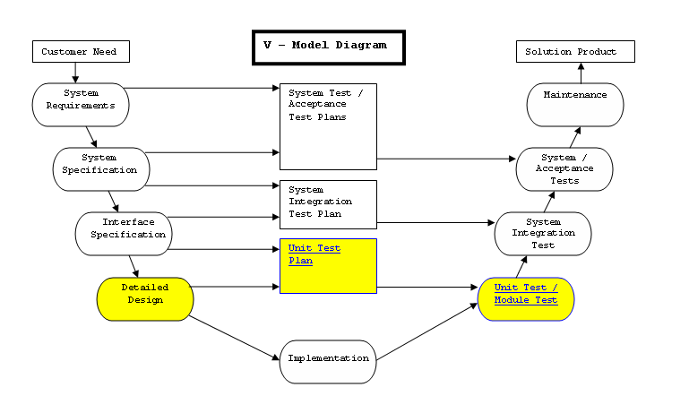
As illustrated in the below V-Model diagram, at this point in the software development process, creation of unit test plans should begin. Unit tests must focus on the implementation details of the various software components of the system under development.