CSCI 5333 Data Base Management Systems
Chapter 9: Mapping from ER or EER to Relational Mode
l
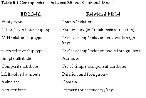
I. From ER to Relational Model
- ER-to-Relational Mapping Algorithm
- STEP 1: For each regular (strong) entity type
E in the ER schema, create a relation R that includes all the simple
attributes of E. Include only the simple component attributes of a composite
attribute. Choose one of the key attributes of E as primary key for R. If
the chosen key of E is composite, the set of simple attributes that form it
will together form the primary key of R.
Example: From Fig. 3.2 to Fig. 7.5
NOTE: The foreign key and relationship attributes,
if any, are not included yet at this step.
- STEP 2: For each weak entity type W in the ER schema
with owner entity type E, create a relation R, and include all simple
attributes (or simple components of composite attributes) of W as attributes
of R. In addition, include as foreign key attributes of R the primary key
attribute(s) of the relation(s) that correspond to the owner entity type(s);
this takes care of the identifying relationship type of W. The primary key
of R is the combination of the primary key(s) of the owner(s) and the partial
key of the weak entity type W, if any.
Example: The DEPENDENT relation
NOTE: It is common to choose the propagate
(CASCADE) option for the referential triggered action (see Section 8.1)
on the foreign key in the relation corresponding to the weak entity type.
- STEP 3: For each binary 1:1 relationship type R
in the ER schema, identify the relations S and T that correspond to the
entity types participating in R. Choose one of the relations—S, say—and include
as foreign key in S the primary key of T. Include all the
simple attributes (or simple components of composite attributes) of the 1:1
relationship type R as attributes of S.
NOTE: It is better to choose
an entity type with total participation in R in the role of S.
(WHY?)
Note:When both participations are total,
an alternative mapping of a 1:1 relationship type
is possible by merging the two entity types and the relationship into a single
relation. (WHY?)
Example: The MANAGE relationship
- STEP 4: For each regular binary 1:N relationship
type R, identify the relation S that represents the participating entity
type at the N-side of the relationship type. Include as foreign key in S
the primary key of the relation T that represents the other entity type participating
in R. (WHY?)
Examples: WORKS_FOR, CONTROLS, and SUPERVISION
- STEP 5: For each binary M:N relationship type
R, create a new relation S to represent R. Include as foreign key attributes
in S the primary keys of the relations that represent the participating entity
types; their combination will form the primary key of S.
Note: We cannot represent
an M:N relationship type by a single foreign key attribute in one of the
participating relations—as we did for 1:1 or 1:N relationship types
. ( Why not?)
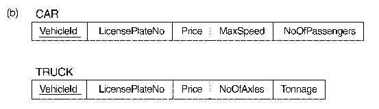
Example: WORKS_ON
NOTE: The propagate (CASCADE) option
for the referential triggered action (see Section 8.1) should be specified
on the foreign keys in the relation corresponding to the relationship R,
since each relationship instance has an existence dependency on each of the
entities it relates. This can be used for both ON UPDATE and ON DELETE.
- STEP 6: For each multivalued attribute A
, create a new relation R. This relation R will include an attribute corresponding
to A, plus the primary key attribute K—as a foreign key in R—of the relation
that represents the entity type or relationship type that has A as an attribute.
The primary key of R is the combination of A and K. If the multivalued attribute
is composite, we include its simple components.
Example: a new relation DEPT_LOCATIONS
NOTE: The propagate (CASCADE) option for the referential
triggered action (see Section 8.1) should be specified on the foreign key
in the relation corresponding to the multivalued attribute for both ON UPDATE
and ON DELETE.
- STEP 7: For each n-ary relationship type
R, where n > 2, create a new relation S to represent R. Include as
foreign key attributes in S the primary keys of the relations that represent
the participating entity types.
Ø
Go to the
Index
II. From
EER to Relational
- STEP 8: Convert each specialization with
m subclasses {S1, S2, . . ., Sm} and (generalized) superclass C, where
the attributes of C are {k, a1, . . ., an} and k is the (primary) key, into
relation schemas using one of the four following options:
Option 8A: Create a relation
L for C with attributes Attrs(L) = {k, a1, . . ., an} and PK(L) = k. Create
a relation Li for each subclass Si, 1 1 i 1 m, with the attributes Attrs(Li)
= {k}D {attributes of Si} and PK(Li) = k.
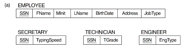
Example: Compare Fig. 9.2(a)
with the EER in Fig. 4.4
Option 8B: Create a
relation Li for each subclass Si, 1 1 i 1 m, with the attributes Attrs(Li)
= {attributes of Si}D {k, a1, . . ., an} and PK(Li) = k.
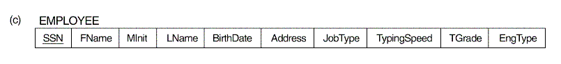
Example: Compare Fig. 9.2(b)
with the EER in Fig. 4.3(b)
Option 8C: Create a single relation
L with attributes Attrs(L) = {k, a1, . . ., an} D {attributes of S1} D .
. . D {attributes of Sm} D {t} and PK(L) = k. This option has the
potential for generating a large number of null values.
Example: Compare Figure
9.2(c) with Figure 4.4.
Question: What would
be the potential problem with this approach?
Option 8D: Create a single
relation schema L with attributes Attrs(L) = {k, a1, . . ., an} D {attributes
of S1} D . . . D {attributes of Sm} D {t1, t2, . . ., tm} and PK(L) = k.
Example: Compare
Figure 9.2(d) with Figure 4.5.
Question: What
would be the potential problem with this approach?
- Mapping of Categories
to Relations
For mapping
a category whose defining superclasses have different keys, it is customary
to specify a new key attribute, called a surrogate key, when creating
a relation to correspond to the category.
For a category whose
superclasses have the same key, such as VEHICLE in Figure 4.8, there
is no need for a surrogate key.
Example:
Compare Fig. 9.4 with Fig. 4.8.
Ø
Go to the
Index
|
 Main Page
Biography
Teaching
Research
Services
Other Links
Last updated: 6/02
|